Front axle group 1 axle
—kg
25 km/h limit 13,500 kg
30 km/h limit 12,500 kg
Tank empty

Chassis, tank, contents and equipment
| Component | Mass, kg | CoG, mm | Front, kg | Rear, kg |
|---|---|---|---|---|
| Total | — |
The original dry tank is 1,200 kg. Its mass scales linearly with the tank percentage. Contents use the current usable capacity and the sheet’s 0.80 kg/L density.
Dry tank = 1,200 × capacity / 26,000
Contents = capacity × 0.80
Tank CoG = 570 + tank length / 2
Tank shell and contents are assumed uniformly distributed along the tank. The midpoint is recalculated from the render geometry, replacing the sheet’s fixed 4,719 mm CoG. An aft extension shifts it by half the added length.
Auxiliary values from columns A–D of 10583 gewichtsberekening v2.ods: FWS 625 × 0.45 = 281.25 kg at 2,500 mm; hose reel 125 kg at 950 mm; panel and fittings 100 kg at 1,850 mm; pump and meter 200 kg at 1,500 mm. The 950 mm hose-reel position is retained as selected, independently of the rear reel in the graphic.
Day Cab weights are taken from page 4 of the supplied DAF XD FAQ specification. DAF WB ends at the middle, driven rear axle, so DAF WB = slider WB + 1,400 mm.
| DAF WB | AE | Front | Rear |
|---|---|---|---|
| 4,700 mm | 1,200 mm | 4,632 kg | 4,261 kg |
| 5,050 mm | 1,200 mm | 4,670 kg | 4,277 kg |
| 5,600 mm | 3,150 mm | 4,588 kg | 4,631 kg |
A separate linear surface is fitted to each axle-group tare using WB and AE. The first two rows determine the wheelbase effect; the third determines the additional rear-overhang effect. The calculated vehicle rear overhang is used as the chassis AE estimate.
DAF tare already includes an 80 kg driver, 306 L of fuel and 41 L of AdBlue. These are not added again. DAF states a ±3% tare tolerance; extrapolation adds further uncertainty. Group weights are summed before rounding; a 1 kg rounding discrepancy in DAF’s printed total is not carried into the calculation.
The rear group is represented by a single support at its middle axle, assuming all three rear axles are lowered and their combined reaction acts there. The original sheet’s 480 mm rear-group offset is replaced by 1,400 mm for this tridem.
Support span = slider WB + 1,400
Rear load = Σ(mass × CoG) / support span
Front load = total mass − rear load
The displayed empty-tank loads remove only the tank contents. The dry tank, equipment and chassis remain.
The base (100%) axle-group limits are 10,000 kg front and 26,600 kg rear. At 25 km/h, multiplying by 1.35 gives 13,500 / 35,910 kg; at 30 km/h, multiplying by 1.25 gives 12,500 / 33,250 kg. The same calculated static loads are checked against each limit; speed changes the comparison limits, not the calculated mass. Loads equal to the limit are not overloaded. The main load indicators use 25 km/h limits, with 30 km/h shown below. Total vehicle mass is displayed without a high-speed overload comparison. Individual rear-axle loads are not inferred.
These are static estimates. Tank CoG, rear-group support position and the extrapolated chassis masses determine the result. Braking, acceleration and liquid movement are not modelled.
Concept geometry. Steering-axle tracks and the 49° inner-wheel angle need confirmation. The envelope assumes a steady turn; it does not simulate steering transitions or tail swing on entry.
Wheelbase is measured from the front axle to the first rear axle, as requested. The three rear axles lie at WB, WB + 1,400 and WB + 2,800 mm. The middle rear axle is the fixed driven axle.
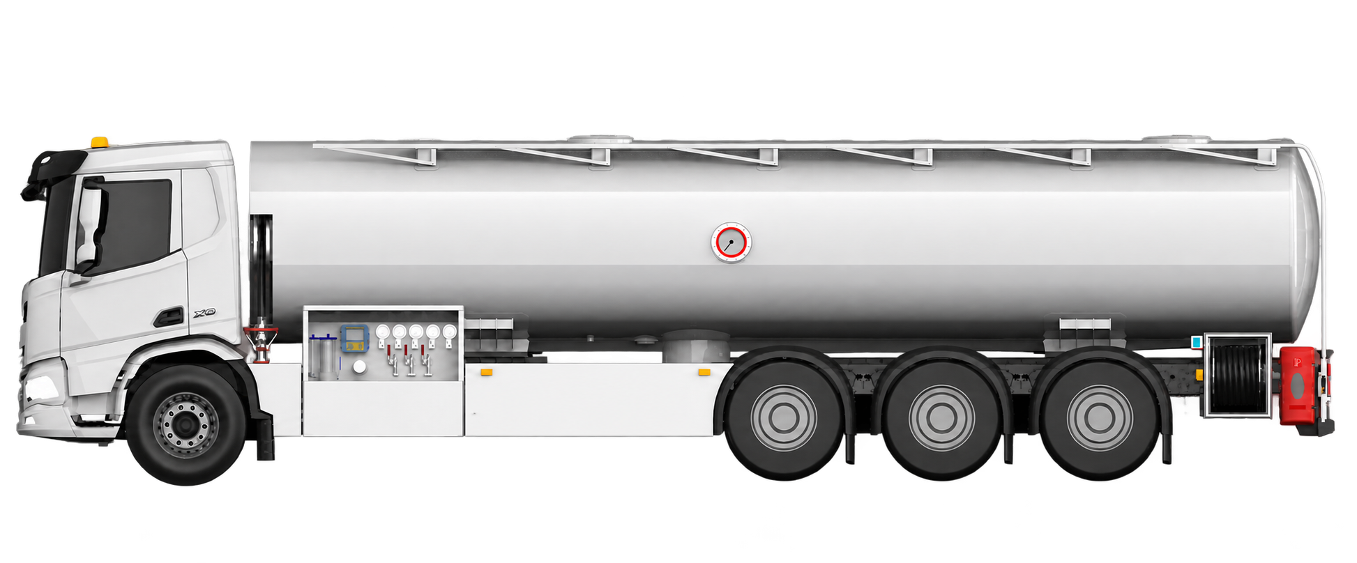
Tank front remains 570 mm behind the front axle. Rear equipment extends 155 mm beyond the tank. These offsets, the approximately 7,800 mm original tank, and the 2,100 mm rear-mount offset are scaled estimates from your render.
Rear overhang = 570 + tank length + 155 − WB − 2,800
Overall length = 1,530 + WB + 2,800 + rear overhang
Hose reel, extinguisher and rear ladder move as a fixed assembly with the tank end. The space behind the last fender remains open. Overlapping combinations are flagged.
Usable volume = 26,000 × tank percentage / 100
Volume follows your linear rule. The axle-load section uses that capacity at 0.80 kg/L; usable filling limits are not independently assessed.
DAF FAQ uses a front steer axle plus steered pusher and tag axles. All wheel axes meet at one instantaneous centre on the driven-axle line. The ideal rear steering angles are derived, not taken from DAF steering software.
L = WB + 1,400 mm
R = L / tan(δ inner) + front track / 2
δ outer = atan(L / (R + front track / 2))
Body radii use a 2,480 mm rectangular envelope including front and rear overhang. The outer radius is the greater of the front and rear corner radii. Tyre paths include half the nominal 315 mm tyre width, with dual tyres on the driven axle.
Map geometry uses ground metres and a geographic conversion before map projection, so its scale stays correct as the map zooms. The red handle is the driven-axle centre; heading 0° is north.
Supplied DAF XD 370 FAQ 8×2 specification · Netherlands · 10 July 2025
Page 4: SB 1.82 m, front overhang 1.53 m, rear spacings 1.41 / 1.40 m. SB is the driven rear track; RB is frame width and TB is overall width, not axle track.
DAF FAQ tridem axle arrangement
Front steering and lift-and-steer axles 2 and 4.
Tbilisi Airport location · © OpenStreetMap contributors
Front, pusher and tag track widths default to an unverified 2,050 mm. The 49° inner-front-wheel angle is your estimate. Replace these values with the build-specific chassis drawing before using results for clearance decisions.
Steady low-speed, no-slip geometry. No articulation, suspension compliance, tyre scrub, mirrors, road slope, obstacle detection or operational clearance allowance.